1. Overview of air suspension development
Suspension is a general term for all force transmission, torque and connection devices between the frame and the axle. Taking the chassis suspension of commercial vehicles as an example, its initial suspension system was leaf spring suspension. With the continuous development of technology, electronically controlled full air suspension has gradually become the mainstream direction of future suspension systems.
Development route of chassis suspension system
In foreign countries, RFS (Road Friendly System) road-friendly suspension system has been vigorously developed by the government and OEMs. This road-friendly suspension system has two very important characteristics: one is the uniform distribution of axle load; the other is the small dynamic load on the ground. As can be seen from Figure 1.1, foreign air suspension has basically gone through two technical routes and four development stages. The North American welding structure technical route: leaf spring suspension-rubber suspension-composite air suspension (partial load of air spring)-electronically controlled air suspension; the European casting structure comfort route: leaf spring suspension-disconnected balance shaft suspension-air suspension-electronically controlled air suspension, and electronically controlled air suspension is the development trend of global chassis suspension.
At present, the application of air suspension abroad is already quite common, and the application of air suspension in my country is also gradually increasing. With the implementation of GB7258-2017 "Technical Conditions for Motor Vehicle Operation Safety", Item 9.4 clearly stipulates that the rear axle of dangerous goods transport trucks with a total mass greater than or equal to 12,000 kg, all dangerous goods transport semi-trailers, and three-axle plate-type and warehouse-type semi-trailers should be equipped with air suspension. The vigorous implementation of this regulation will greatly promote the rapid development of air suspension in China.
2. Characteristics of air suspension system
2.1 Reduce vehicle weight
Air suspension uses air springs instead of traditional elastic elements such as leaf springs, which is about 200~500 kg lighter than the same level of leaf spring suspension.
2.2 Good driving smoothness
Air suspension is a nonlinear suspension with variable stiffness. When the sprung mass changes, the stiffness changes accordingly to keep the vehicle height the same when empty and fully loaded, and the natural frequency of the suspension remains basically unchanged. According to the needs, different airbag working heights can be selected to obtain the ideal natural frequency, so as to obtain good driving smoothness. Smoothness determines the comfort of passengers and the integrity of cargo.
2.3 Improve the handling stability of the whole vehicle
The air suspension is light in weight and low in spring stiffness. When driving at high speed, the tire has strong adhesion to the ground and short braking distance; when turning, the tendency of over-steering and under-steering is reduced, and the steering stability is strong, which improves the handling stability of the whole vehicle.
2.4 Ensure driving safety
The air pressure in the air spring directly reflects the sprung mass. The air pressure can be taken as a signal to control the air pressure in the brake cylinder to control the braking force during braking, which better ensures driving safety.
2.5 Adjustable vehicle height
In addition to automatically adjusting the design setting of the vehicle height, the height control valve can also be used to adjust the vehicle body to raise or lower (kneel) to improve the passability or facilitate passengers to get on and off the vehicle. For trucks or semi-trailers, the cargo box floor can be maintained at the same height as the loading and unloading platform.
2.6 Road friendliness
When a vehicle equipped with air suspension is driving at high speed, the suspension stiffness is low and the wheel dynamic load is small, which reduces the damage to the road surface caused by high-speed vehicles.
3. Composition of air suspension system
The air suspension system mainly consists of air springs, guide mechanisms, height control valves, shock absorbers, lateral stabilizer bars and control systems.
A heavy-duty commercial vehicle air suspension system
3.1 Air spring
The air spring is an elastic element that uses the reaction force of compressed air inside the rubber airbag as the elastic restoring force. Its stiffness changes nonlinearly, usually when the load increases, the stiffness also increases, so the ride comfort is also better. The air medium friction of the air spring is extremely small, there is almost no noise when working, and the absorption and sound insulation performance of high-frequency vibrations are good.
According to the structural form, air springs can be divided into: capsule air springs, membrane air springs, and sleeve air springs.
Membrane air springs: have good load-bearing capacity and consistent elastic characteristics in a wide range of working heights, and have low stiffness.
Capsule air spring: Generally, it can only have good load-bearing capacity within the set working height range, and has high stiffness.
Sleeve air spring: Generally used in passenger cars and cab suspensions, similar to membrane air springs, and the stiffness of the air spring can be adjusted by adjusting the piston shape.
Leaf springs and coil springs have a low downward jump stroke when unloaded, and a very low upward jump stroke when fully loaded, which makes it easier to penetrate the suspension. Air springs can ensure that the upward and downward jump strokes are the same when unloaded and fully loaded, so they can meet the comfort consistency of unloaded and fully loaded.
3.2 Guide mechanism
The guide mechanism of the air suspension system usually has the following types:
(1) Leaf spring guide mechanism
The leaf spring not only plays a guiding role, but also plays the role of a part of the elastic element. At the same time, the left and right guide arms and the bridge tube together form a stabilizer bar structure, which plays a strong anti-roll stabilization role. This guide mechanism has a simple layout and is light in weight.
Leaf spring guide mechanism
(2) Multi-link guide mechanism
The upper V-shaped thrust rod and the double lower I-shaped thrust rod form a 4-link guide mechanism. In addition to bearing the longitudinal force, the upper V-shaped thrust rod also bears the lateral force when turning. The reasonable arrangement of the length of the upper and lower thrust rods can make the changes in the wheelbase and front wheel positioning parameters within the specified range, ensuring good driving stability. However, its structure is complex and the force points of the body are concentrated, which is not conducive to the load-bearing body without a frame.
Multi-link guide mechanism
(3) Multi-link fork arm guide mechanism
The use of fork arms instead of upper V-shaped thrust rods and anti-roll stabilizer bars not only reduces weight, but also greatly simplifies the structure of the suspension system, but also requires higher strength and good elasticity for the fork arms.
Multi-link fork arm guide mechanism
3.3 Height control valve
The function of the height control valve is to adjust the internal air pressure of the air spring and keep the air spring within a certain height range to balance the external load. Generally, the pressure drop of the height control valve in 24 hours should be less than 0.02MPa, the fatigue number should be greater than 3 million times, the maximum working pressure is generally 1.5-2MPa, and the applicable temperature range is -40℃-70℃.
Height control valve
3.4 Shock absorber
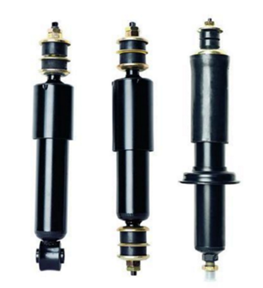
The shock absorber plays the role of attenuating the amplitude in the suspension system, which can slightly increase the natural frequency of the system. The passive shock absorber is a compromise between the comfort and handling stability of the suspension system, and the damping ratio is generally selected to be around 0.25. This will cause the problem of large no-load damping and small full-load damping, and may also cause poor high-frequency vibration isolation effect. Therefore, a semi-active damping adjustable shock absorber was invented.
Passive shock absorber
CDC adjustable damping shock absorber, as the actuator of the CDC semi-active suspension system, is its key component and core technology. There are two ways to realize the automatic continuous adjustment of shock absorber damping: electromagnetic valve controlled throttle adjustable damping shock absorber, that is, the position of the electromagnetic valve core is controlled by PWM, and then the throttle area of the electromagnetic valve is changed, so that the damping force of the shock absorber body is continuously and steplessly changed; magnetorheological adjustable damping shock absorber (MRF), that is, using magnetorheological fluid as the working fluid, by controlling the magnetic field strength and utilizing the friction resistance between molecules, the continuous and stepless adjustable change of the magnetorheological shock absorber damping is realized. The response time of electromagnetic valve controlled shock absorber is generally within 35ms, and the response time of magnetorheological fluid is within 10ms, but the cost of magnetorheological fluid is relatively high.

CDC adjustable damping shock absorber
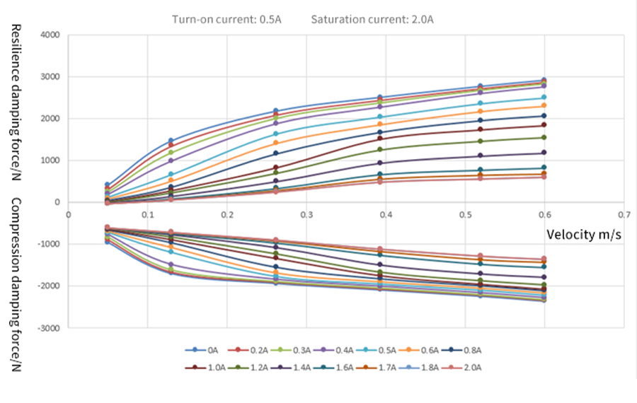
Figure 3.10 Typical P-V characteristic curve of semi-active damping shock absorber: When there is no PWM control, the CDC solenoid valve has no flow, so it is the body damping, and the damping force is the largest. Between 0 and 0.5A is the dead zone of the solenoid valve, and there is basically no flow. As the duty cycle (current) increases, the gap between the solenoid valve core and the valve seat increases, the flow increases, and the damping force gradually decreases, reaching saturation at around 2A, that is, the damping force is the smallest. In each speed range, the maximum and minimum damping force ratio can reach up to 6 times, so it can ensure that the vehicle system provides a smaller damping force when a small damping is required, and vice versa. The traditional passive shock absorber only corresponds to the P-V curve under a certain current, which affects the comfort and handling stability of the vehicle system.

Typical P-V characteristic curve of semi-active damping shock absorber
3.5 Lateral stabilizer bar
The purpose of the lateral stabilizer bar is to improve the anti-roll capability of the vehicle and ensure that the vehicle has good steering characteristics. The stabilizer bar assembly is generally composed of stabilizer bars, stabilizer bar hangers, hanger support and other parts.


